Arduino Uno Explained: Microcontroller Architecture, GPIO, Registers & Hardware Fundamentals – Part 1
Arduino Uno Explained: Understanding the Microcontroller, GPIO Architecture & Hardware Registers – Part 1
Introduction: Before You Start Programming Arduino
Arduino is one of the most popular platforms for learning electronics, microcontrollers and embedded systems. From simple LED blinking projects to industrial automation, robotics, IoT devices and smart home systems, Arduino has become a common starting point for electronics enthusiasts and engineers.
However, many beginners start by writing Arduino code without understanding what actually happens inside the board.
For example:
- What happens inside the microcontroller when you write
digitalWrite(13, HIGH)? - How does the microcontroller know whether a pin is an input or an output?
- What are GPIO ports, and why are they grouped into Port B, Port C and Port D?
- What is a hardware register?
- How does the CPU communicate with GPIO pins?
- What are register addresses, and why are they important in embedded programming?
- How does an analog voltage become a digital number?
Understanding these fundamentals will help you move beyond basic Arduino programming and become a better embedded systems developer.
In this first part of our Arduino learning series, we will explore the hardware architecture of the Arduino Uno R3, understand its main microcontroller, examine its GPIO architecture and learn how hardware registers control physical pins.
Our goal is simple: Understand the hardware first, then learn how to control it through code.
1. What Is Arduino Uno?
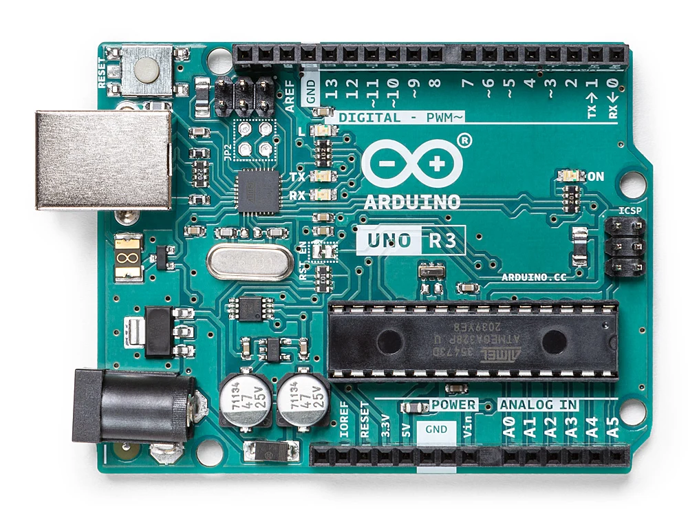
Arduino Uno is a microcontroller development board based on the ATmega328P, an 8-bit AVR microcontroller developed by Microchip Technology.
The board provides an easy way to connect the microcontroller to external electronic components such as:
- LEDs
- Push buttons
- Sensors
- Motors and motor drivers
- Relays
- LCD displays
- Communication modules
- Other microcontrollers
Arduino Uno includes supporting hardware such as a USB interface, voltage regulator, clock source, reset circuit and programming interface.
These supporting components make it easier to develop embedded applications without designing every supporting circuit yourself.
Arduino Uno R3 – Main Specifications
| SpecificationDetails | |
| Main Microcontroller | ATmega328P |
| Architecture | 8-bit AVR RISC |
| Operating Voltage | 5V |
| Clock Frequency | 16 MHz |
| Flash Memory | 32 KB |
| SRAM | 2 KB |
| EEPROM | 1 KB |
| Digital I/O Pins | 14 |
| PWM Outputs | 6 |
| Analog Inputs | 6 |
| ADC Resolution | 10-bit |
| UART | 1 |
| SPI | 1 |
| I2C | 1 |
| USB Interface | ATmega16U2 on official Uno R3 |
Note: These specifications refer to the classic Arduino Uno R3, not the newer Uno R4.
2. Understanding the Main Microcontroller IC

The most important component of Arduino Uno is its main microcontroller IC: ATmega328P.
A microcontroller is a small computer integrated into a single chip. It contains several important functional units:
- CPU (Central Processing Unit)
- Flash Memory
- SRAM
- EEPROM
- GPIO Controllers
- Timers and Counters
- ADC (Analog-to-Digital Converter)
- Communication Interfaces
- Interrupt Controller
- Watchdog Timer
All these internal peripherals work together to execute your embedded application.
2.1 CPU – Central Processing Unit
The CPU is the brain of the microcontroller.
It executes instructions stored in Flash Memory and controls the internal peripherals.
The ATmega328P uses an 8-bit AVR RISC architecture.
What does 8-bit mean?
An 8-bit CPU generally processes data in 8-bit registers and operations. Its general-purpose registers are 8 bits wide.
For example:
uint8_t value = 255;
An 8-bit unsigned variable can represent values from 0 to 255.
The CPU performs operations such as:
- Arithmetic operations
- Logical operations
- Data movement
- Bit manipulation
- Conditional branching
- Peripheral control
The AVR CPU uses a register-based architecture with 32 general-purpose 8-bit working registers.
2.2 Flash Memory
Flash Memory stores the program or firmware that the microcontroller executes.
For Arduino Uno R3:
- Total Flash Memory: 32 KB
- Approximately 0.5 KB is reserved for the standard bootloader.
Flash memory is non-volatile, meaning its contents remain stored even after the power is disconnected.
When you upload an Arduino sketch, the compiled program is stored in Flash Memory.
2.3 SRAM – Static Random Access Memory
SRAM is the temporary working memory of the microcontroller.
It stores:
- Global variables
- Local variables
- Function parameters
- Stack data
- Runtime application data
The ATmega328P contains only 2 KB of SRAM.
Unlike Flash Memory, SRAM loses its contents when the power is removed.
This is why memory management is important when developing applications for small microcontrollers.
2.4 EEPROM – Electrically Erasable Programmable Read-Only Memory
EEPROM is non-volatile memory used to store data that must remain available after power loss.
For example:
- Device configuration
- User settings
- Calibration values
- Stored parameters
The ATmega328P contains 1 KB of EEPROM.
Unlike SRAM, EEPROM retains its stored information even when the microcontroller is turned off.
2.5 Memory Comparison
| MemorySizeMain PurposePower Off | |||
| Flash | 32 KB | Program/Firmware | Data retained |
| SRAM | 2 KB | Runtime variables | Data lost |
| EEPROM | 1 KB | Persistent settings | Data retained |
3. Understanding Arduino Uno Hardware Architecture

Arduino Uno is not just a microcontroller IC. Several external components are connected to support its operation.
Let's understand the important components.
3.1 Main Microcontroller – ATmega328P
This is where your application runs.
It handles GPIO operations, sensor readings, communication, timers and other application tasks.
3.2 USB-to-Serial Interface – ATmega16U2
On the official Arduino Uno R3, an ATmega16U2 acts as a USB-to-serial interface.
It allows a computer to communicate with the ATmega328P through USB.
Some third-party Arduino Uno-compatible boards use USB-to-serial chips such as CH340 instead.
3.3 Crystal or Clock Source
The official Uno R3 uses a 16 MHz ceramic resonator as the main clock source for the ATmega328P.
The clock provides timing signals that allow the CPU and peripherals to operate at a defined frequency.
Why is the clock important?
Without a clock source, the CPU cannot execute instructions normally.
Clock frequency affects:
- Instruction execution speed
- Timer operation
- UART baud rate generation
- PWM timing
- Other peripheral operations
3.4 Voltage Regulator
Arduino Uno can receive power from different sources.
The onboard voltage regulation circuitry provides a regulated supply for the board.
Typical recommended external input voltage is 7V–12V.
The board's main operating voltage is 5V.
3.5 Reset Circuit
The reset circuit allows the microcontroller to restart its execution from the beginning.
Reset can occur through:
- The onboard Reset button
- USB programming interface
- External reset signal
- Power-on reset circuitry
3.6 Power and Ground
Important power pins include:
| PinPurpose | |
| VIN | External input supply |
| 5V | Regulated 5V supply |
| 3.3V | 3.3V output |
| GND | Ground |
| RESET | Microcontroller reset |
| IOREF | Board logic voltage reference |
Important: Applying an incorrect voltage to GPIO pins or power inputs can permanently damage the microcontroller.
4. Understanding GPIO – General Purpose Input/Output
GPIO stands for General Purpose Input/Output.
GPIO pins are programmable digital connections that allow a microcontroller to communicate with external electronic components.
A GPIO pin can generally operate in two basic modes:
- Input Mode
- Output Mode
4.1 GPIO Input Mode
In input mode, the microcontroller reads the electrical logic level present on the pin.
For example, a push button can be connected to a GPIO pin.
When the button is pressed, the input voltage changes and the microcontroller can detect that change.
Typical digital logic levels:
| LogicApproximate Voltage on 5V Uno | |
| LOW | 0V |
| HIGH | 5V |
Actual input thresholds are specified in the ATmega328P datasheet.
4.2 GPIO Output Mode
In output mode, the microcontroller controls the output logic level of a pin.
For example:
- HIGH: Output logic high
- LOW: Output logic low
An LED connected through a suitable current-limiting resistor can be controlled through a GPIO output.
4.3 What Is a GPIO Port?
Beginners often confuse Arduino pin numbers with microcontroller port names.
They are not the same thing.
Arduino Uno groups its ATmega328P GPIO pins into three hardware ports:
- Port B
- Port C
- Port D
Each port contains up to 8 individual bits, corresponding to its physical pins.
For example:
- PB0 means Port B, Bit 0.
- PB1 means Port B, Bit 1.
- PC0 means Port C, Bit 0.
- PD2 means Port D, Bit 2.
The ATmega328P has 23 general-purpose I/O pins distributed across these three ports, although not all are exposed as separate Arduino Uno header pins.
5. Arduino Pin Mapping – Arduino Pins vs AVR Port Pins
This is one of the most important concepts to understand before learning register-level programming.
Arduino uses simple pin numbers such as D2, D3, D8 and D13.
However, the ATmega328P does not internally identify these pins using Arduino's digital pin numbering system.
It uses Port and Bit names.
5.1 Digital Pin Mapping
| Arduino PinAVR PortBitSpecial Function | |||
| D0 | PD0 | Bit 0 | RX |
| D1 | PD1 | Bit 1 | TX |
| D2 | PD2 | Bit 2 | INT0 |
| D3 | PD3 | Bit 3 | PWM / INT1 |
| D4 | PD4 | Bit 4 | GPIO |
| D5 | PD5 | Bit 5 | PWM |
| D6 | PD6 | Bit 6 | PWM |
| D7 | PD7 | Bit 7 | GPIO |
| D8 | PB0 | Bit 0 | GPIO |
| D9 | PB1 | Bit 1 | PWM |
| D10 | PB2 | Bit 2 | SPI SS / PWM |
| D11 | PB3 | Bit 3 | SPI MOSI / PWM |
| D12 | PB4 | Bit 4 | SPI MISO |
| D13 | PB5 | Bit 5 | SPI SCK / Built-in LED |
5.2 Analog Pin Mapping
Arduino Uno provides six analog input pins.
| Arduino PinAVR PortBitAlternate Function | |||
| A0 | PC0 | Bit 0 | ADC0 |
| A1 | PC1 | Bit 1 | ADC1 |
| A2 | PC2 | Bit 2 | ADC2 |
| A3 | PC3 | Bit 3 | ADC3 |
| A4 | PC4 | Bit 4 | ADC4 / SDA |
| A5 | PC5 | Bit 5 | ADC5 / SCL |
Important observation:
Arduino pin D13 is actually PB5 inside the microcontroller.
This mapping allows us to control the physical pin directly through hardware registers without using Arduino's digitalWrite() function.
6. Understanding Hardware Registers
Now we are moving toward the most important concept in register-level embedded programming.
A hardware register is a special memory-mapped or I/O-mapped location used to control and monitor the internal hardware peripherals of a microcontroller.
For GPIO operations, the ATmega328P provides three important registers for each port.
- DDRx – Data Direction Register
- PORTx – Data Register
- PINx – Input Pins Register
Here, x represents the port name: B, C or D.
6.1 DDRx – Data Direction Register
The DDRx register determines whether each GPIO pin operates as an input or output.
Each bit controls the direction of one corresponding pin.
| Register BitValueConfiguration | ||
| 0 | 0 | Input |
| 0 | 1 | Output |
For example:
DDRB = 0b00000001;
This configures PB0 as an output and PB1–PB7 as inputs.
Another example:
DDRD = 0b11111111;
This configures all eight Port D pins as outputs.
6.2 PORTx – Data Register
The PORTx register controls output logic levels when a pin is configured as an output.
It also controls the internal pull-up resistor when the pin is configured as an input.
For example:
PORTB = 0b00000001;
When PB0 is configured as an output, this sets PB0 HIGH.
Similarly:
PORTB = 0b00000000;
This sets all Port B output bits LOW.
6.3 PINx – Input Pins Register
The PINx register allows the CPU to read the actual logic levels present on the physical GPIO pins.
For example:
uint8_t input_state = PINB;
This reads the current input states of all eight Port B pins.
An interesting AVR feature: Writing a logic 1 to a bit in the PINx register toggles the corresponding bit in the PORTx output register.
This behavior is useful for understanding AVR GPIO hardware at a deeper level.
7. GPIO Register Address and Memory Mapping
Now let's understand what a register address means.
Every hardware register has a specific address in the microcontroller's register address space.
The CPU uses these addresses to access hardware registers.
The ATmega328P uses a separate I/O address space as well as data-memory addresses for its I/O registers.
For example, Port B registers have the following addresses:
7.1 Port B Register Addresses
| RegisterI/O AddressData Memory Address | ||
| PINB | 0x03 | 0x23 |
| DDRB | 0x04 | 0x24 |
| PORTB | 0x05 | 0x25 |
7.2 Port C Register Addresses
| RegisterI/O AddressData Memory Address | ||
| PINC | 0x06 | 0x26 |
| DDRC | 0x07 | 0x27 |
| PORTC | 0x08 | 0x28 |
7.3 Port D Register Addresses
| RegisterI/O AddressData Memory Address | ||
| PIND | 0x09 | 0x29 |
| DDRD | 0x0A | 0x2A |
| PORTD | 0x0B | 0x2B |
Why are there two addresses?
AVR provides an I/O address space for peripheral registers. These same registers are also accessible through the data memory address space, which includes an offset of 0x20 for these registers.
This distinction is important when studying the AVR instruction set, datasheet and low-level C programming.
For example, the C header file avr/io.h provides register names such as DDRB, PORTB and PINB, so you normally do not need to manually enter their addresses.
8. Understanding Bit Manipulation
Microcontrollers frequently control individual hardware functions by setting, clearing or reading individual bits.
A register is typically 8 bits wide.
For example:
Bit Position:

Bit 7  Bit 6  Bit 5  Bit 4  Bit 3  Bit 2  Bit 1  Bit 0
  0      0      0      0      0      0      0      0
Each bit can control a separate GPIO pin.
8.1 Set a Bit
To set PB5 HIGH without affecting other bits:
PORTB |= (1 << PB5);
8.2 Clear a Bit
To set PB5 LOW:
PORTB &= ~(1 << PB5);
8.3 Toggle a Bit
To toggle PB5:
PORTB ^= (1 << PB5);
8.4 Read a Bit
To check the current state of PB5:
if (PINB & (1 << PB5))
{
    // Pin is HIGH
}
else
{
    // Pin is LOW
}
These operations are called bit manipulation techniques.
They are widely used in embedded firmware because they allow precise control of hardware registers.
9. Understanding ADC – Analog-to-Digital Converter
Not every electronic signal is digital.
Sensors such as:
- Temperature sensors
- Light sensors
- Potentiometers
- Analog pressure sensors
- Analog voltage sensors
can provide continuously varying voltage levels.
The microcontroller cannot directly process a continuously varying analog voltage using its digital logic.
This is why the ATmega328P contains an Analog-to-Digital Converter (ADC).
The Arduino Uno uses a 10-bit ADC.
9.1 What Does 10-Bit ADC Mean?
The ADC converts an analog voltage into a digital number.
For an N-bit ADC:
[
\text{Number of Levels}=2^N
]
For a 10-bit ADC:
[
2^{10}=1024
]
Therefore, the ADC output range is:
[
0 \text{ to } 1023
]
9.2 Example ADC Calculation
Assume:
- ADC Reference Voltage = 5V
- Analog Input Voltage = 2.5V
- ADC Resolution = 10-bit
The approximate ADC count is:
[
ADC=\frac{V_{in}}{V_{ref}}\times(2^{10}-1)
]
[
ADC=\frac{2.5}{5}\times1023
]
[
ADC\approx512
]
So the ADC produces approximately 512.
The reverse calculation is:
[
V_{in}\approx\frac{ADC\times V_{ref}}{1023}
]
If the ADC count is 512:
[
V_{in}\approx\frac{512\times5}{1023}
]
[
V_{in}\approx2.502V
]
This is how an analog voltage becomes a digital value that the microcontroller can process.
Note: Actual ADC conversion behavior depends on the reference source, analog input conditions and ADC characteristics.
10. Understanding PWM – Pulse Width Modulation
PWM stands for Pulse Width Modulation.
It is a technique used to control the average power delivered to a load by rapidly switching a digital output ON and OFF.
Arduino Uno provides six PWM-capable pins:
- D3
- D5
- D6
- D9
- D10
- D11
What Is Duty Cycle?
Duty cycle represents the percentage of time a PWM signal remains HIGH during one complete period.
[
Duty\ Cycle=\frac{T_{ON}}{T_{Period}}\times100
]
For example:
| Duty CycleSignal Behavior | |
| 0% | Always LOW |
| 25% | HIGH for 25% of the period |
| 50% | HIGH for half the period |
| 75% | HIGH for 75% of the period |
| 100% | Always HIGH |
PWM is commonly used for:
- LED brightness control
- DC motor speed control
- Fan speed control
- Power control applications
Important: PWM is not a true analog voltage output. It is a digital waveform whose average value can be controlled. Proper filtering or a suitable driver circuit may be required depending on the application.
11. Understanding Communication Peripherals
A microcontroller does not work alone. It frequently communicates with other ICs, sensors and controllers.
The ATmega328P includes several communication peripherals.
11.1 UART / USART
UART is commonly used for serial communication.
Arduino Uno uses UART through:
- D0 – RX
- D1 – TX
Applications include:
- Serial Monitor communication
- GPS modules
- GSM modules
- Serial sensors
- Other microcontrollers
11.2 SPI – Serial Peripheral Interface
SPI is a synchronous communication interface.
Arduino Uno uses:
| SignalArduino Pin | |
| MOSI | D11 |
| MISO | D12 |
| SCK | D13 |
| SS | D10 (common default) |
SPI is commonly used with:
- SD card modules
- Display controllers
- Flash memory
- High-speed peripheral ICs
11.3 I2C – Inter-Integrated Circuit
I2C uses two communication lines:
- SDA – Data
- SCL – Clock
On Arduino Uno:
- SDA = A4
- SCL = A5
I2C is commonly used with:
- LCD I2C backpacks
- RTC modules
- EEPROM ICs
- Environmental sensors
- Other I2C peripherals
12. Timers, Counters and Interrupts
The ATmega328P contains three timer/counter units:
| TimerResolutionCommon Applications | ||
| Timer0 | 8-bit | Timekeeping and PWM |
| Timer1 | 16-bit | Precise timing and PWM |
| Timer2 | 8-bit | Timing and PWM |
Timers can generate periodic events, measure time intervals, count external pulses and generate PWM signals.
What Is an Interrupt?
An interrupt is a mechanism that temporarily changes normal program execution so the CPU can respond to an important event.
For example:
- A button state change
- A timer overflow
- UART data reception
- ADC conversion completion
- External hardware events
Instead of continuously checking everything, the microcontroller can respond to configured interrupt events.
Interrupts are an important concept in real-time embedded systems.
13. How Does Arduino Code Actually Control Hardware?
Now let's connect everything we have learned.
Suppose you want to turn ON the onboard LED connected to Arduino Uno pin D13.
The physical pin mapping is:
Arduino D13
    |
    v
ATmega328P PB5
    |
    v
Port B, Bit 5
    |
    v
DDRB / PORTB Registers
The CPU changes the appropriate register bits, and the GPIO hardware drives the physical output.
This is the fundamental relationship between software and hardware.
Arduino High-Level GPIO Control
Arduino provides easy-to-use functions:
void setup()
{
    pinMode(13, OUTPUT);
}

void loop()
{
    digitalWrite(13, HIGH);
    delay(1000);

    digitalWrite(13, LOW);
    delay(1000);
}
Here, Arduino handles the low-level register operations internally.
Direct Register-Level GPIO Control
The same LED can be controlled using AVR hardware registers:
#include <avr/io.h>
#include <util/delay.h>

int main(void)
{
    // Configure PB5 (Arduino D13) as output
    DDRB |= (1 << DDB5);

    while (1)
    {
        // Turn LED ON
        PORTB |= (1 << PORTB5);
        _delay_ms(1000);

        // Turn LED OFF
        PORTB &= ~(1 << PORTB5);
        _delay_ms(1000);
    }
}
In this example:
DDRBconfigures the GPIO direction.DDB5selects bit 5 of the data direction register.PORTBcontrols the output state.PORTB5selects the output bit.- The CPU executes these operations directly through the AVR register interface.
This is the foundation of register-level embedded programming.
Note: This example uses AVR-GCC conventions. Compile it with an AVR toolchain configured for ATmega328P and 16 MHz. It is not a complete Arduino IDE sketch as written.
14. Electrical Safety and GPIO Limitations
Understanding GPIO architecture is not enough. You must also understand its electrical limitations.
For Arduino Uno R3:
| ParameterSpecification | |
| Operating Logic Voltage | 5V |
| Recommended GPIO Current | 20 mA per pin |
| Absolute Maximum GPIO Current | 40 mA per pin |
| 3.3V Output Maximum Current | 50 mA |
The 40 mA figure is an absolute maximum stress limit, not a recommended operating current. Supply and port-group current limitations also apply.
Important Hardware Design Rules
- Always use a current-limiting resistor when driving a bare LED.
- Never connect a 12V signal directly to a 5V GPIO pin.
- Use transistor or MOSFET drivers for motors and high-current loads.
- Use suitable protection for inductive loads such as relays and motors.
- Make sure external circuits share a common ground when required.
- Check the microcontroller datasheet before connecting external hardware.
These precautions are essential for reliable embedded hardware design.
15. Practical Learning Checklist
Before moving to Arduino programming, make sure you understand these concepts:
| TopicWhat You Should Understand | |
| Microcontroller | What ATmega328P does |
| CPU | How instructions are executed |
| Flash | Where firmware is stored |
| SRAM | Where runtime data is stored |
| EEPROM | How persistent data is stored |
| GPIO | How digital input/output works |
| Port B/C/D | How physical pins are grouped |
| Pin Mapping | How Arduino pins map to AVR pins |
| DDRx | How pin direction is configured |
| PORTx | How output and pull-up are controlled |
| PINx | How input state is read |
| Register Address | How CPU accesses hardware registers |
| Bit Manipulation | How individual bits are controlled |
| ADC | How analog voltage becomes digital data |
| PWM | How digital switching controls average power |
| UART/SPI/I2C | How peripherals communicate |
| Timers | How hardware generates timing events |
| Interrupts | How hardware events trigger CPU actions |
16. What's Next? Arduino Learning Series – Part 2
Now that you understand the hardware architecture of Arduino Uno, it is time to learn how to program it.
In the next part of this series, we will start with Arduino programming fundamentals.
Planned topics include:
- Introduction to Arduino IDE.
- Understanding
setup()andloop(). - C/C++ programming fundamentals for embedded systems.
- Variables, data types and operators.
pinMode(),digitalWrite()anddigitalRead().- LED blinking and push-button interfacing.
- Understanding
analogRead()andanalogWrite(). - Writing your first register-level GPIO program.
We will gradually move from high-level Arduino functions to direct hardware register programming.
Don't just learn how to use Arduino. Understand how the microcontroller actually works.
Official Technical References & Further Reading
For accurate technical information, always refer to the official documentation and microcontroller datasheets.
- Arduino Uno R3 – Official Documentation
- Arduino Uno R3 – Official Datasheet
- ATmega328P – Microchip Official Datasheet
- Arduino Language Reference
About IoT Tech BD
IoT Tech BD provides electronics, embedded systems, IoT development and automation solutions. We believe in understanding hardware from the fundamentals to advanced engineering.
Our goal is to help students, hobbyists and aspiring embedded engineers develop practical knowledge of microcontrollers, electronics and real-world embedded system design.
Learn. Build. Innovate with IoT Tech BD.